

 The conventional powder metal process involves several steps to produce a final part. A vital component to this process is compaction tooling, which is responsible for giving powdered metal parts their required net shape and attributes.
Powder metallurgy (PM) compaction tooling design is essential to reducing costs and maximizing design features. In its simplest form, tooling is a process – the planning, design, and engineering of tools to mold a component that’ll fit and perform correctly within an assembly.
The FAQs compiled below will help you understand the big-picture approach of using PM tooling to make a sturdier and more cost-effective product:
8 Questions for a Powder Compaction Tooling Pro
To summarize the process and how it affects how your design’s transformation into a finished part, I’ve selected eight customer FAQs:
Q: What is powder compaction tooling?
A: Powder compaction tooling is an assembly of individual components that go into a die set. Together, they create a closed cavity that holds loose powder prior to compaction.
Q: What exactly does powder compaction tooling do?
A: Manufacturers design powder compaction tools with the raw materials, press, and component shape in mind. The tool’s design should mirror a part’s shape and attributes.
A basic set of powder metallurgy tooling used for single-level components includes:
- Upper punch
- Lower punch
- Die
- Core rod
Pressing a part involves taking a “column” of powder metal, gravity-feeding it into a compaction die cavity, and compressing it under high pressure. This forms a net- or near-net-shape part.
With the materials now available, powder metallurgy manufacturers can produce a component to a desired shape much faster than other metal forming techniques, such as machining or casting. PM tooling also allows suppliers to mass-produce components off a single set of compaction tools. This makes it a much lower-cost option than other forming methods and still gives customers the same integrity they would get from competing forming technologies.
Q: What mechanical factors influence the design of powder metal tooling?
A: Each tool set has its own set of requirements and challenges, but a tool design engineer typically works through the same processing questions:
- What size press is needed to compact the component?
- How many levels will it take to produce the component?
- What is the wall thickness of the component?
- What are the different lengths on the component?
- Is there enough compaction ratio to produce the component?
- Are there PM-unfriendly shapes (bevels, chamfers, radii, side holes, tapped holes) that might hinder tool life?
Parts with increased levels or complexity will have more complex tooling, which allows for control of density and ejection from the die.
Even though multilevel parts are more intricate, the design thought process is ultimately pretty similar to single-level parts.
Q: What are the most important goals in creating compaction tooling?

A: There is a lot of team collaboration that goes into designing powder compaction tooling. Common tooling design goals are:
- Cost-effectiveness: Every production step should influence tooling design, so we examine that first for the most efficient way to manufacture the part.
- Quality: The component should meet or exceed the customer’s performance requirements.
- Durability: The manufacturer gives careful consideration to material selection and surface treatments for optimizing tool life.
Q: What steps go into the design of a powder compaction tool?
A: Tooling design for powder metallurgy has several steps and considerations before fabrication. These considerations ensure that projects are cost-effective and that tooling sets are designed with the endurance and toughness needed for long-continuous compaction runs.
A PM product engineering team will initiate four design tasks prior to tool manufacturing:
1. Assess the Component’s Design for PM Manufacturability
To ensure the component design is optimized for manufacturability in a powder metallurgy setting, a full evaluation is in order. A team assesses the component’s print for:
- Overall shape
- Surface area and length
- Wall thickness
- Material properties
- Compaction ratios
- Levels required to compact the component
- Secondary operation considerations
Throughout this assessment, suppliers look for opportunities to enhance a part’s manufacturability.
The prototype tooling will ultimately become the production tooling, so selecting a powder metal tool steel depends on the part’s intended end use. Factors to consider include:
- Hardness
- Toughness
- Wear resistance
- Availability
- Price
The goal at this point is to balance these factors and pick the grade of tooling material that will give the best performance.
2. Generate a Solid Model

A design engineer creates a solid model of the molded part, adjusting for the part considerations listed above. It’s important to consider the dimensional change for the raw material prior to tooling manufacture.
3. Create a Parametric Press Stack-Up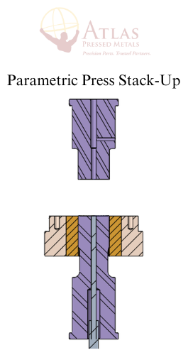
Using the generated part model (above), the engineer builds a solid model assembly with 3D modeling software. This allows for accurate visualization and manipulation of the tooling components relative to one another.
4. Create Individual Tool Drawings
The designer creates a 2D drawing for the tool models. This includes every member of the assembly.
Each drawing consists of:
- Materials
- Tolerances
- Finish
- Coatings
Q: How are the tools themselves manufactured?
A: During the tool manufacturing stage, the 2D drawings inspire the creation of the tooling router. The 3D models facilitate CNC programming.

Experienced tool and die makers use a variety of equipment to manufacture compaction tooling:
- Manual or CNC lathe
- Manual or CNC mill
- Heat treatment furnace
- Wire EDM
- Ram EDM
- Various types of grinders
- Polishing machines
Q: How do you ensure the tooling will hold up?
A: Powder metallurgy tooling needs to endure hundreds of thousands of production cycles. Powder metallurgy suppliers run tool management plans in-house for this reason. A plan might include:
- Documentation (specs and conditions)
- Maintenance schedule
- Performance monitoring
Each component presents a learning curve when estimating tool life. However, past experience and components with similar geometries provide insight into choice of materials and design considerations.
More Resources on Powder Metallurgy & Tool/Die Design
The entire manufacturing process influences tooling design, and vice versa. As processes and tooling technology improve, so will powder metallurgy buyers’ end results. Innovations in the works include:
- Stronger materials
- More powerful presses
- Improved sintering conditions
- Processing upgrades
To keep up on the latest shortcuts to a more cost-effective design, visit our full library:

COMMENTS