.png?width=300&name=Webpage%20Headers%20(8).png)
Holes
- Holes in the pressing direction can be round, D-shaped, include keyways, splines, etc.
- Hole tools are called core rods. The core rods must remain straight and not buckle during compaction or ejection, or off-dimension problems may result.
- Lightening holes are frequently added to large parts to reduce projected pressing area, thus making parts easier to press.
- Side holes have to be made after a sintering operation, usually by machining.
Wall Thickness
- Die fill is all-important; do not make walls thinner than 0.060 inch (1.52mm) as a general rule.
- Long, thin walls result in fragile tooling and parts with tendencies toward variations in density.
- Where the ratio of length-to-wall thickness is as high as 8 to 1 or more, special precautions must be taken to achieve uniform fill. Variations in density are unavoidable.
Flatness
- Total measured flatness obviously depends on surface area.
- Thin parts tend to distort more than thick parts during sintering or heat treatment.
- Repressing improves flatness.
- Projection bosses are easier to bring to flat than entire face areas.
Fillets and Radii
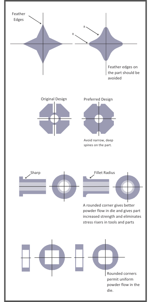
- Generous fillet radii are most desirable.
- Tooling with such fillets is more economical, longer lasting.
- Parts made with generous fillets are made more easily, more quickly.
- Parts made with fillets have greater structural integrity.
Tapers and Drafts
- Draft is generally not required or desired on sides of parts. While draft on outer sections for ejection is sometimes worthwhile, it demands careful timing of the tools and slower production rates.

.png)
Chamfers and Bevels
- Chamfers, rather than radii, are necessary on part edges to prevent burring. For example, on a bushing a 30 degree angle and a 0.005 to 0.015 inch (0.13 to 0.38mm) flat to eliminate feather edges are the preferred practice.
- Large angle chamfers may be produced by bevels in dies or core rods. Production rates would be slowed with such tooling because of caution in preventing die-fill and between-tool powder wedging problems.
Countersinks
- A countersink is a chamfer around a hole for a screw or bolt head.
- When the countersink is formed by a punch, a 0.010-inch (0.25mm) nominal flat is essential for avoiding sharp, fragile edges on the punch.
Flanges
- A comparatively small flange, step, or over-hang can often be produced by carving a shelf or step in the die.
- Too large a flange causes ejection difficulties. Bottom flange edge and juncture radii should be generous.
Bosses
- Boss forming cavities may be located in punch tools. Cavities may not be too deep in relation to part height, and draft angles should be at least 7 degrees, preferably 15 degrees, per side to avoid sticking of the compacted boss to the punch.
Undercuts
- Undercuts on the horizontal plane cannot be made since they prevent part ejection from the die.
- Annular grooves may be machined as a secondary operation.
- On a part where a juncture undercut is needed to allow fit-up to a dead corner, an alternative approach is recommended.
Need a Solution?
Ask Us a Question
Contact Information
Mailing Address
125 Tom Mix Dr.
P.O. Box P
DuBois, PA 15801
USA
Phone
Fax
Testimonial
"Our Engineering team works directly with Atlas Pressed Metals to achieve our company goals. Atlas is always very helpful, gives us on-time delivery and the sales reps are always willing to research to get answers for our needs.”
- Amanda S., Associate Buyer | Healthcare Industry


.png?width=300&name=Webpage%20Background%20(4).png)
