.png?width=300&name=Webpage%20Headers%20(1).png)
What is Powder Metallurgy (PM)?
![]()
The conventional powder metallurgy (PM) process, often referred to as “press and sinter,” is a method of manufacturing precision metal parts. The process includes materials selection; compaction; sintering; and, if required, secondary operations like steam treating, machining, lapping or grinding.
The PM process is cost-effective in producing simple or complex parts at, or very close to, final dimensions. The parts can range in size from 0.68 g (.0015 lbs.) to 6800 g (15 lbs.).
Since each part requires a custom set of tooling, PM is most suitable for moderate-to-high-production rates, which can range from a few hundred to several thousand parts per hour.
While PM was initially used for simple shapes like bushings and bearings, today it also produces complex, multilevel components.
Conventional "Press & Sinter" Powder Metal Process
![]()
Our comprehensive powder metal process and services have accelerated success for Atlas customers, designing components that meet and exceed their application requirements. New manufacturing technologies and equipment have expanded PMs reach into new industries. Widely recognized as a superior process for a variety of applications, the conventional “press and sinter” method includes:

Materials Selection
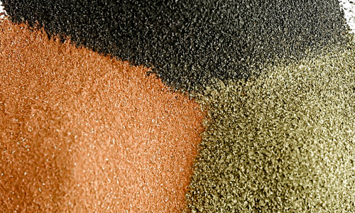
The powder metal process begins with a material blend containing powdered metal and alloying elements. A part’s requirements and desired properties -- such as strength or hardness -- determine what material blend is best.

Compaction
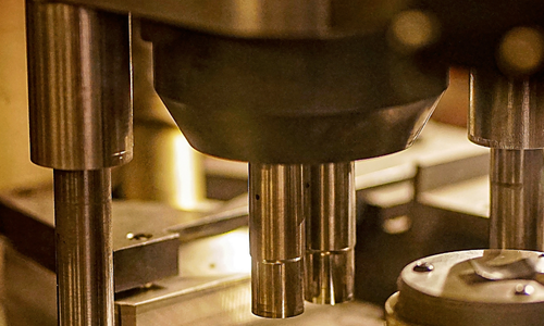
A press compacts a material blend into a net-shape or near-net-shape, “green” part. The part is able to retain its dimensional form because the powder’s irregular particle shapes interlock during compaction. Prior to sintering, a part’s strength is comparable to that of an aspirin tablet, but varies based on material.

Sintering
The sintering process ensures that a part is durable and ready for the wear and tear of real-life use. The “green” compacted parts are heated in a sintering furnace that allows the particles to alloy and bond, which creates the final material characteristics.

Secondary Operations
Secondary operations, if necessary, add more functions or features to a sintered part. Examples of these operations include turning, milling, grinding, and deburring.
Advantages of Powder Metallurgy
![]()
- Efficient, versatile, and cost-effective solutions
- Long-term performance and reliability in complex applications for diverse markets
- High-quality and consistent parts for all-volume demands
- Diverse design capabilities ranging from single-level parts to complex structural components
- Range of material blends with heat-treatable options for increased strength and wear resistance
- Controlled porosity for self-lubrication or filtration
- Close dimensional tolerances for complex designs
- Net-shape or near-net-shape capabilities minimizing machining operations
- Conversion of multi-part assemblies into one component, saving time, SKUs, and money
Powder Metallurgy Solutions
![]()
Structural Parts
Atlas’s state-of-the-art metallurgical and engineering capabilities, combined with our wide variety of presses, sintering furnaces, and in-house secondary operations, offer our structural component customers the opportunity for high-quality components, reduced turnaround, and cost savings.
.png?width=392&height=235&name=Website%20Images%20500%20X%20300%20(1).png)
Gears
Our state-of-the-art automation and material handling systems and our in-house expert metallurgists allow Atlas to produce multilevel gears with internal configurations to tight tolerances to eliminate or reduce the need for additional operations.
Learn More →Bearings
Our company's first market was powder metal bearings. Custom metal bearings and bushings crafted through PM allows for the impregnation of parts with lubrication, which extends run-time and minimizes maintenance.
Conversions
Powder metal conversions are emerging as a game-changer, offering customers cost efficiency by reducing material waste and minimizing secondary operations. This makes it a more economical choice compared to traditional manufacturing methods.
Recognized Green Technology
![]()
Powder Metallurgy is recognized as a Green Technology. The powder metal process when compared to competing forming technologies is more environmentally friendly and sustainable. The key aspects include:
- PM uses 15% less energy than other processes like casting and forging
- Net shape or near net shape parts yields less than 5% scrap

.png)
Need a Solution?
Ask Us a Question
Contact Information
Mailing Address
125 Tom Mix Dr.
P.O. Box P
DuBois, PA 15801
USA
Phone
Fax
Testimonial
"Our Engineering team works directly with Atlas Pressed Metals to achieve our company goals. Atlas is always very helpful, gives us on-time delivery and the sales reps are always willing to research to get answers for our needs.”
- Amanda S., Associate Buyer | Healthcare Industry


.png?width=286&height=172&name=Website%20Images%20500%20X%20300%20(3).png)
.png?width=300&name=Webpage%20Background%20(4).png)
